
Tira Led Rgb Ws2812b Ws2812 300 Leds 5 Metros 5v Waterproof
Paga en cuotas
¡Última disponible!
+1000 ventas
Compra ProtegidaSe abrirá en una nueva ventana, recibe el producto que esperabas o te devolvemos tu dinero.
12 meses de garantía de fábrica.
Información sobre el vendedor
- 100%
de compradores lo recomiendan
- 16 años
vendiendo en Mercado Libre
- 1038
ventas concretadas


Descripción
DESCRIPTION
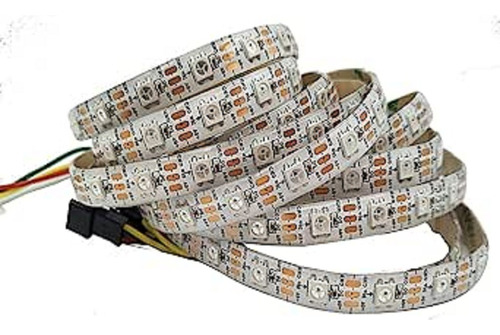
Individually addressable full color RGB LEDs on a long 5 meter / 16.4ft flexible strip. Pixel density is 60 pixels (LEDs) per meter, 300 in total.
We offer these for use with our WS2812 Adapter for our Prototyping System for Teensy 4.1 baseboard, but can be used with just about any microcontroller such as an Uno or ESP32 to create interesting displays and effects.
PACKAGE INCLUDES:
WS2812 Addressable RGB LED Strip, 5m, 300 LED, White, Non-waterproof, 5V
Male pigtail cable for connecting to screw terminals
KEY FEATURES OF WS2812 ADDRESSABLE RGB LED STRIP
RGB SMD LED in 5050 (5 x 5mm) package (x300)
Built-in WS2812B LED drivers (x300)
Flexible 5m / 16.4ft long strip can be cut to any length
Built-in JST-SM input and output connectors
Built-in additional power pick-up points
Adhesive backing
High brightness
Fully addressable using 1-wire interface
High quality construction with copper die heat sinks and solid gold bond wires
IP30 non-waterproof – Indoor use only
5V operation
These LEDs are the same type that are sold under the brand name of NeoPixels where each LED is separately addressable.
The communication used with the LEDs is a 1-wire interface specific to these devices. There are several libraries available to handle the interfacing details including the Adafruit NeoPixel library and the more advanced FastLED library, both of which are supplied with the Arduino IDE.
There are no specific addresses for the LEDs, rather the color data for each is sent down the wire sequentially with the first LED taking the first color data that comes down the wire, the second LED takes the second color data and so on. After all LEDs are updated, a global command is given to display the new data simultaneously.
The individual LEDs are mounted on 0.5m long flexible PCBs that are connected together into a 5m / 16.4ft long continuous strip. The strip is flexible and can be curved as needed, but avoid sharp bends. The back has an adhesive liner that can be used to permanently mount the strip if desired onto a clean dry surface.
Connections
These strips have JST-SM 3-pin connectors on both ends. The connectors supply 5V, data and ground.
JST-SM Connector (Female):
Red – 5V
Green – Data In
White – Ground
JST-SM Connector (Male):
Red – 5V
Green – Data Out
White – Ground
The input connector which is on the outside of the roll is a female connector for connecting to a microcontroller. A male pig-tail is included in the package for connecting this end to screw terminals such as found on the WS2812 Adapter or it can be adapted for other connection requirements.
The output end of the strip has a male connector for optionally attaching to one or more additional strips to increase the length.
Both connectors include an extra 5V and ground wire stub so that additional power can be optionally supplied to the LED strip at one or both ends or at multiple points if several strips are connected together to avoid excessive voltage drop along the long length of the strip(s). An excessive voltage drop will cause the far end of the strip to be dimmer or change color or stop working altogether. If these wires are not used, heat shrink can be applied or they can be taped back on themselves to avoid any risk of shorting or they can be cut off.
Supplying Power
These LED strips operate at a nominal 5V. The WS2812B chip spec is 3.5 – 5.3V so there is some flexibility in the voltage range that they will function over, but keep in mind that there will be some voltage drop along the long length of the strip so try to stick with something close to 5V for best performance.
The strips typically must be powered from a separate 5V power supply. Don’t attempt to connect them to the 5V from the microcontroller board unless you are going to light only a small number of LEDs at a time and the brightness is kept down. When using a separate power supply, ensure a common ground exists between the MCU and the LED power supply.
The LED strips should always be connected to the power source with the power turned off to avoid possible damage.
For most benchtop applications, the power can be supplied through the 3-pin input connector only. If pushing higher power levels or stringing multiple strips together, additional power can be supplied to the far end of the cable through the red and white power pigtails if needed. In very long strings, power can be input into multiple points along the chain.
The current requirements will vary a lot depending on how the LEDs are being driven. Keep in mind that at maximum brightness and displaying full white (all red/green/blue LEDs fully on), each LED can take up to 60mA / 0.3W, so the full strip can take up to 90W which is 18A!
When working with it on the bench, you can keep brightness down around 10% which is still fairly bright and get by with something like a 2A 5V power source.
For large arrays at high brightness, careful consideration needs to be given about the power supplies to use and the size of wiring needed to distribute power feed a power hungry setup.
It is recommended to have a large 1000uF electrolytic capacitor on the input power leads to help avoid damage to the LED strip from the turn-on current surge. If used with the WS2812 Adapter, it includes this capacitor.
Driving the LED Strip
The LEDs are driven using a 1-wire serial interface.
The logic level used to drive the strip should be 5V for best operation. If using with a 3.3V microcontroller with the strip powered from 5V, a level shifter on the data pin should be used to drive the strip at 5V logic levels. The WS2812 Adapter includes a 74HCT245 line driver to provide the proper level shifting. If the strip power is lowered toward the minimum of 3.5V, it can be possible to directly drive the strip from 3.3V logic.
The drive line should also include a series resistor in the 100-470 ohm range to dampen signal back reflections. The WS2812 Adapter uses 100 ohm resistors.
The data is driven at a 800Kbps rate with fairly tight timing requirements. A software library is typically used to drive these strips which makes them very easy to use as it hides all the messy details.
Though the LEDs are referred to as being addressable, that is not true in the strictest sense. The LEDs are actually accessed sequentially in a simple but effective cascading manner. When an LED receives data, it doesn’t know what its position is in the strip, it simply takes the first 24-bit of data it receives, stores it and passes the rest of the data down the wire. The next LED similarly takes the first 24-bit of data that it gets and passes the rest along and so on. After all LEDs are updated, a global command is given to display the new data simultaneously on all of the LEDs.
LED Number Limitations
There is no inherent limit in the number of LEDs that can be driven in a chain as each LED in the strip has a signal reshaping circuit before passing the data to the next LED, but several practical limitations will limit the number of LEDs that can be used in an application.
Power: As noted above, each LED can draw up to 60mA, so at worst case (full white at maximum brightness), this strip can consume up to 18A (90W) of power. That is then multiplied by the number of strips in use. Power tends to be the main limitation in the maximum number of LEDs that are used.
Processor speed: Updating the LEDs require fairly precise timing of the data line which is updated at a 800kbps rate. The more LEDs there are, the more processing time is required to update the string. Faster MCUs can handle more LEDs without slowing updates down. Teensy excels at handling larger arrays of these LEDs.
RAM: The software uses RAM for LED pixel information. More LEDs = more RAM required. This limitation will vary greatly on the MCU being used to drive the LEDs but is not a concern for most small to medium projects. Again, due to its large memory capacity, Teensy is the best suited for large projects.
Changing the Strip Length
Besides chaining strips together to lengthen them, an individual strip can be shortened by cutting between the individual LEDs. A line through the center of the copper pads show the basic cut point.
This also permits some creativity by cutting the strip and soldering wires to the pads or using right angle adapters that are available to sharply change direction such as going from horizontal to vertical direction.
Note that there are arrows that shows the direction of data flow if you are working with sections of strip with the ends cut off. Also visible in this picture is a 0.1uF MLCC capacitor that is mounted next to each pixel to help filter the power to the WS2812B chip inside of the LED package.
OUR EVALUATION RESULTS:
LEDs tend to be fun to play with in general and RGB LEDs are the most fun of all, especially when you have a lot to play with and you only need one pin to control them.
These addressable LEDs are frequently used for color accents around objects or to create artistic or otherwise interesting displays. Now’s the chance to make that Knight Rider display you always wanted.
The program below uses the Adafruit NeoPixel library to exercise the strip. It is a shortened version of the strandtest example program that is installed when the library is downloaded. It has some of the excess comments removed for brevity. For full comments open the example program.
Since we are using the WS2812 Adapter, we are connecting the DI input (green wire) to Pin 24 of the MCU, but this can be changed to any available data pin such as pin 6 on an Uno. Connect 5V (red wire) to a suitable 5V power source and GND (white wire) to ground. Ensure the LED power ground is common with the MCU ground.
Preguntas y respuestas
¿Qué quieres saber?
Pregúntale al vendedor
Nadie ha hecho preguntas todavía. ¡Haz la primera!